Lab1: Getting Started with Active-HDL
Create, Edit, Compile and
Simulate a Counter Design Using Active-HDL
Revised
by: Basawaraj
Active-HDL Version: Student Edition 9.3
Last modified: 02-10-2014
Introduction
Purpose of Lab1
- Learn to use Active-HDL design tools to
edit, compile, simulate and debug a VHDL design.
- Implement a decade-counter using VHDL
About Active-HDL
Active-HDL is an EDA (Electronic Design Automation) tool for VHDL based
design that runs on PC. Digital designs can be easily implemented using this
tool. All the necessary functions are integrated into this environment, from
design entry to compiler, debugger and simulator. Some useful features such as
design wizards are also used to make design more convenient. I am sure you will
find the tool very intuitive and easy to use.
Contents of Lab1
- Implement a Decade-Counter.
- Function description:
1. Count the number of clk, which ranges from 0 to 9
2. Count can be reset
asynchronously.
- I/O Port: clk, reset: IN; q[3..0]: OUT
- Sample design
--Counter VHDL
ibrary
IEEE;
--library definition
use IEEE.std_logic_1164.all;
use IEEE.std_logic_unsigned.all;
entity Counter
is
--entity definition
port (
clk:in std_logic;
reset: in std_logic;
q: out std_logic_vector(3 downto 0)
);
end Counter;
architecture
Counter of Counter
is
-- Architecture definition
begin
process(clk,reset)
-- Process definition
variable qtemp: std_logic_vector(3
downto 0); -- temporary variable for
output q[3..0]
begin
if reset='1' then
qtemp:="0000";
-- Reset asychroniously
else
if clk'event and clk='1'
then
-- Counting state
if qtemp<9 then
qtemp:=qtemp+1;
-- Counter increase
else
qtemp:="0000";
-- Return the zero state
end if;
end if;
q<=qtemp;
-- Output
end if;
end
process;
-- End Process
end
Counter;
-- End Architecture
Getting
Started
Starting Active-HDL
Creating a New Design
Ports Wizard
Design Browser
Editing Code
Starting simulation
Assigning stimulators
Let’s simulate
Debugging
- debugging
Design Entry
Starting Active-HDL
To start working with the program go to the Start
-> All Programs -> Aldec program group
and click the Active-HDL Student Edition.
Active-HDL Student Edition should start loading and the following dialog
appears.
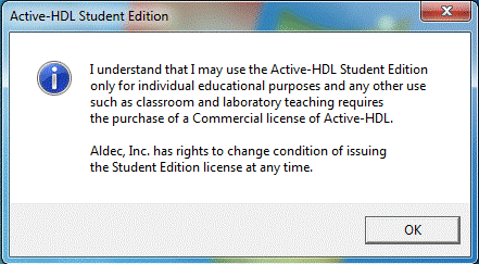
Click “OK” to continue. The following dialog appears asking if you want
to create a new workspace (i.e. project).
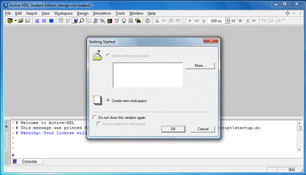
Click “OK” to create a new workspace or project. This brings up the
dialog for creating the new workspace.
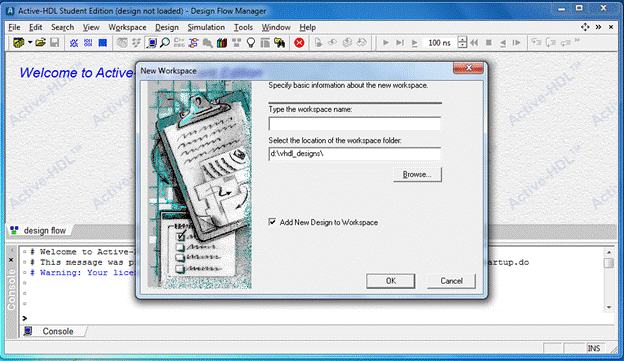
Provide the workspace name, here “lab1”, and click “OK”. You can change
the folder where the workspace will be saved.
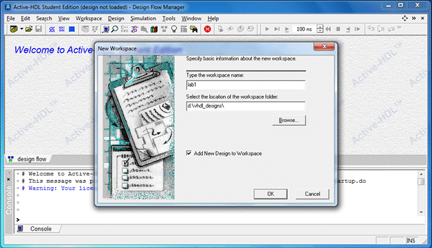
This brings up the “New Design
Wizard”.
Creating a New
Design
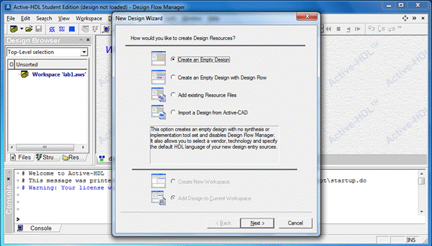
“New Design Wizard” has four options.
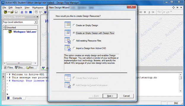
Select “Create an Empty Design” option.
Click “Next” to continue. This bring up the “Property Page” dialog.
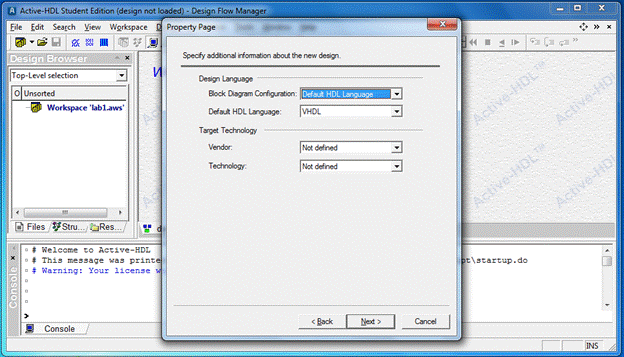
Make the following selections for
the various options in the property page:
1. Design Language:
1. Block Diagram Configuration: Default HDL
Language (the default option)
2. Default HDL Language: VHDL
2. Target Technology:
1. Vendor: Not defined (the default option)
2. Technology: Not defined (the default option)
Note: - Selecting proper
target technology options helps to make sure the design considerations fit the
actual FPGA being targeted. These options are not critical for the purpose of
this lab; but for the final project, if using Basys 2
Spartan-3E board, use the following options for Target Technology
a. Vendor: Xilinx 14x
b. Technology: SPARTAN3E
Note: - Do check the options available in the
Vendor and Technology fields. You might require them to answer any questions
given at the end of this or other labs.
Click “Next” to continue. The “New
Design Wizard” pops up asking for the design name.
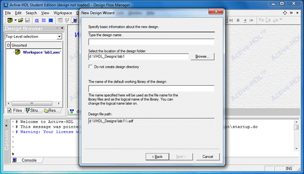
Enter “Tutorial” as the design name.
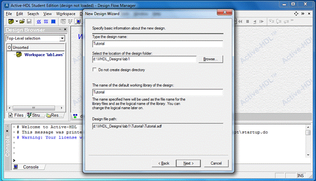
Click “Next” to continue. This brings up the wizard with the
specifications of the design.
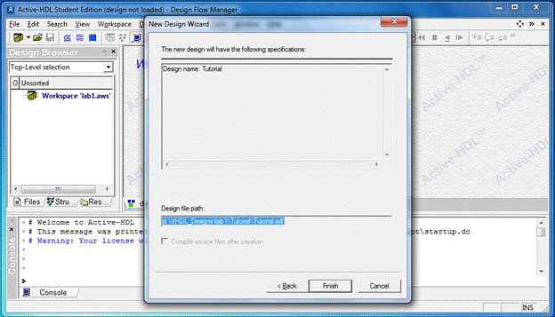
Click “Finish” to accept the
specifications. This brings out the “Design Flow Manager”. The next section
introduces the “Design Browser”.
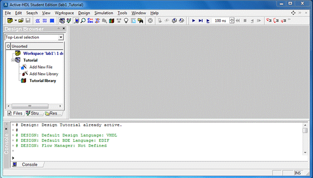
The “Design Browser” is a window showing the design contents. Design
Browser is visible in the previous image that appeared as a result of the
previous operations, and is shown below.
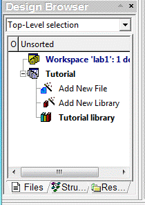
Double-click the “Add New File” in
the Design Browser to get the Add New File window.

In the Add New File window select ‘VHDL Source Code” icon under “Empty
Files” tab. Enter Counter for the
Name Empty File item.
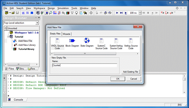
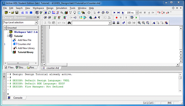
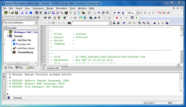
Click “OK” to get an empty VHDL file. Make sure that the VHDL Source Code
icon is highlighted under the Empty Files tab. You will see the following
window.
NOTE: - Adding
new file to the design can also be accomplished by the following steps.
In the Design Browser window, right-click “Add New File”. On the popup menu under “New” click on “VHDL Source”.
Alternatively, under menu item File -> New click on VHDL Source.
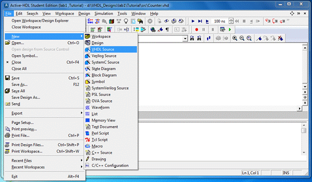
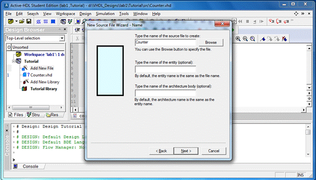
This bring up the “New Source File Wizard”, click
“Next” to continue.

Enter the source file name, eg. Counter, and
click “Next” to continue.
This brings up the “Ports” section of the “New Source File Wizard”.
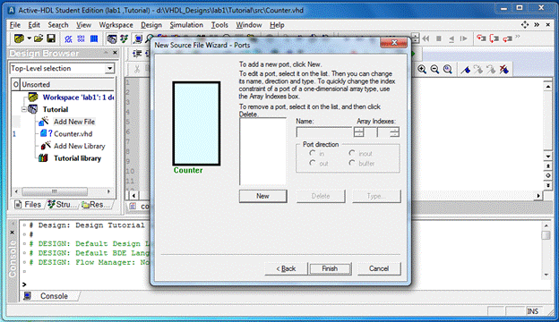
Click on “Finish” to add the file to the design.
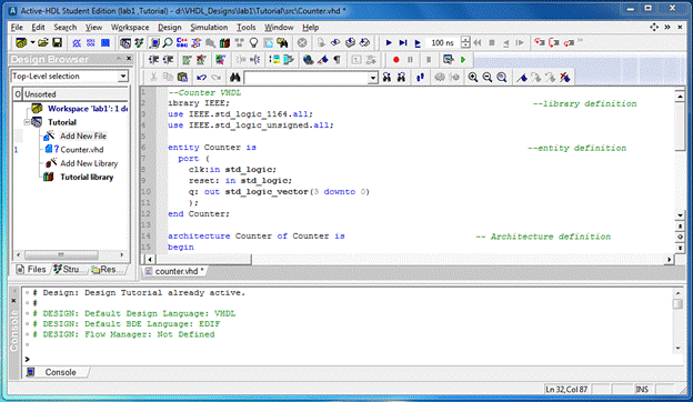
Now you can edit the VHDL code. An easy way is to copy the previous code and paste
into the empty file.
Editing Code
The HDL Editor is a text editor with VHDL keywords coloring and standard
editing features.
If you have followed all the steps you will see the window above.
OK! Now you finish the design entry. The next thing you should do is to
compile your design.
Save the design using Ctrl + s
or through File -> Save (or File -> Save All).
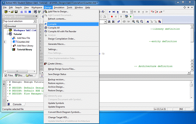
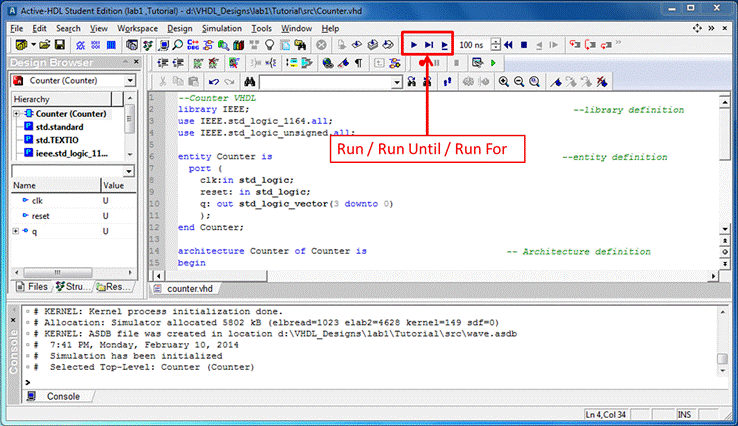
Compiling
Select Counter.vhd
in the “Design Browser”, then go to the Design menu,
click the Compile option from the menu or press F11 (or Compile All, especially
if you have to compile a design with multiple source files) to compile Counter.vhd file.
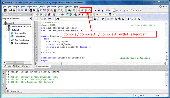
You can also use the toolbar icons, high lightened on the image below,
to compile the design.
If there is any error, the file icon changes to red error, erroneous
lines are underlined and the VHDL console window contains the error
description. You need to correct the error based on the error information in
the VHDL Console first line. (l for library is missing.)
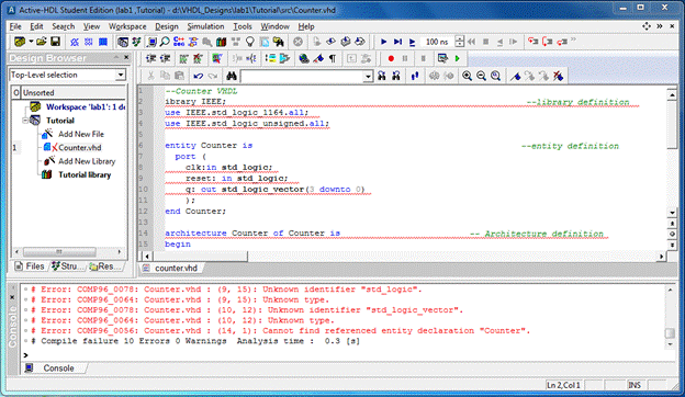
Add the letter "l" and compile to error-free state.
Note: - Though you had only one
error (in only the second line) the compiler gives 10 errors! Hence when
compiling your code, always start from the first line in which you see an
error.
Exercise: - Delete the
semi-colon (;) at the end of the third line and try compiling. What happens?
(Look at the errors shown in the ‘Console’ window.)
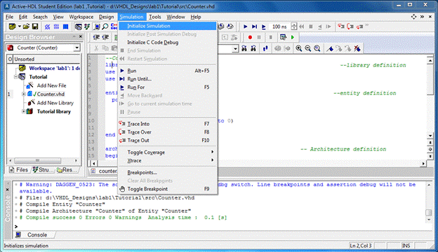
Simulation
To begin a
simulation, you have to first initialize the simulator using the “Initialize
Simulation” option from the “Simulation” menu.
After the
simulator has been initialized, you have to open a new Waveform window. Click
the New Waveform toolbar button ![]() , high lightened in the image below.
, high lightened in the image below.
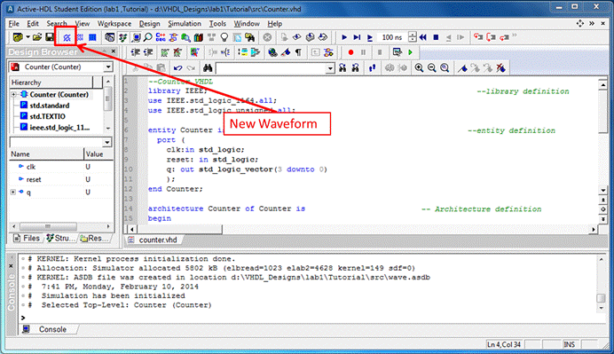
The new
Waveform window appears.
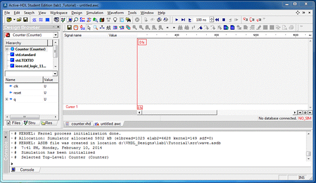
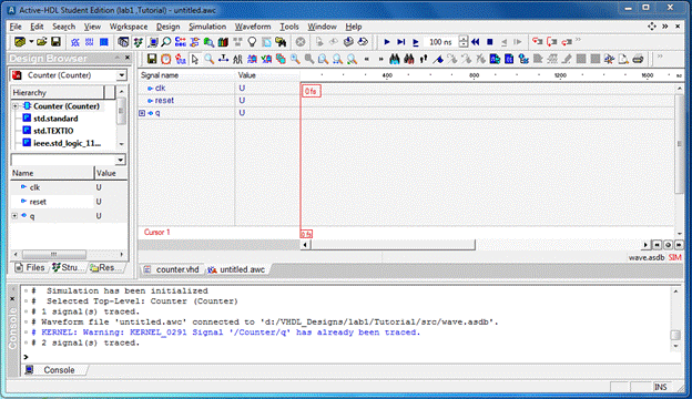
Signals
for simulation can be added using the drag and drop feature. On the Structure
tab of the Design Browser you have to select the component whose ports you want
to observe and simply holding the left button, drag it to the left-hand section
(pane) of the waveform window and release the button (typical drag-and-drop
operation). Follow the procedure described above to drag all ports of the
components Counter to the waveform window.
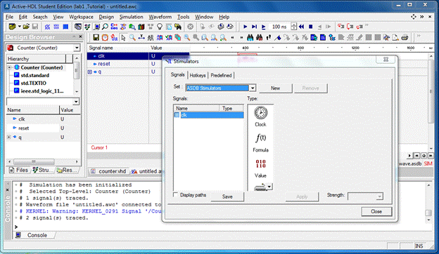
Assigning stimulators
To simulate the design it is essential that all inputs are assigned
appropriate signals. To do this use the inbuilt
simulators option. To access this: select the signal, right-click and select
“Simulators” option. For example, if assigning simulators to the clk signal,
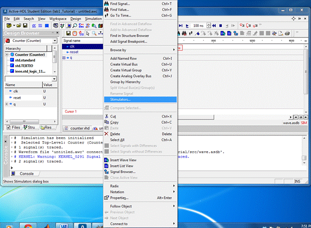
Clicking on the “Simulators” item brings
the Simulators window.
Choose the “Clock” icon from the “Type” box in the “Simulators” dialog.
Place the mouse pointer in the “Frequency” box and set the value to 50 MHz.
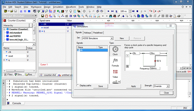
Click the “Apply” button to assign the simulator. Now, select the RESET
signal in the Waveform window, and then select the “Formula” item from the
“Type” box in the Simulators dialog.
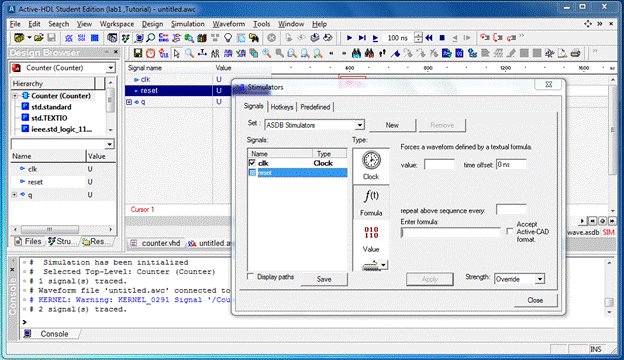
Put 1 0,0 1ns in the “Enter formula” box. This
is read as follows: “reset” signal is initially high (‘1’ at 0 ns) and goes low
at 1 ns (‘0’ at 1 ns) and continues to remain low till
the end of the simulation.
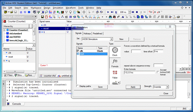
Click “Apply” and then “Close”.
Let's simulate!
You can choose the command of “Run” (Alt+F5) or “Run Until” or “Run For”
(F5) from main menu of Simulation.
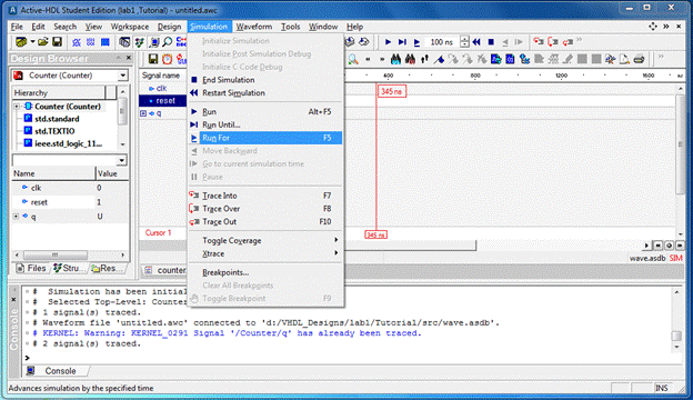
Run keeps the simulator running forward .Run For
runs the simulator for defined time every step and Run Until runs the
simulators in the defined time.
You can
change the formula expression to see what will happen according to different
waveforms of the reset signal.
Debugging
You can perform either a single step simulation, which is useful for
source code debugging, or a continuous simulation, for high-speed design
analysis and comparing results. You can try all three ways to figure how your
Counter works.
Active-HDL
allows walking along the code during the step simulation. The code window is
automatically opened after one of the step simulation buttons has been clicked.
There are three
commands for step simulation:
![]() The Simulation
/Trace Into command executes a single VHDL statement.
If a subprogram call is encountered, the execution descends into the subprogram
body.
The Simulation
/Trace Into command executes a single VHDL statement.
If a subprogram call is encountered, the execution descends into the subprogram
body.
![]() The Simulation
/Trace Over command executes a single VHDL statement. If a subprogram call is
encountered, the statements contained within the subprogram body are skipped.
The Simulation
/Trace Over command executes a single VHDL statement. If a subprogram call is
encountered, the statements contained within the subprogram body are skipped. ![]() The Simulation /Trace Out
command completes the currently executed subprogram. If subprograms are nested,
the command completes the innermost subprogram only. The statement which is to
be executed next is yellow highlighted in the HDL Editor window.
The Simulation /Trace Out
command completes the currently executed subprogram. If subprograms are nested,
the command completes the innermost subprogram only. The statement which is to
be executed next is yellow highlighted in the HDL Editor window.
Go through all the toolbar options/icons to learn their functions. The
simulation result is as follows.
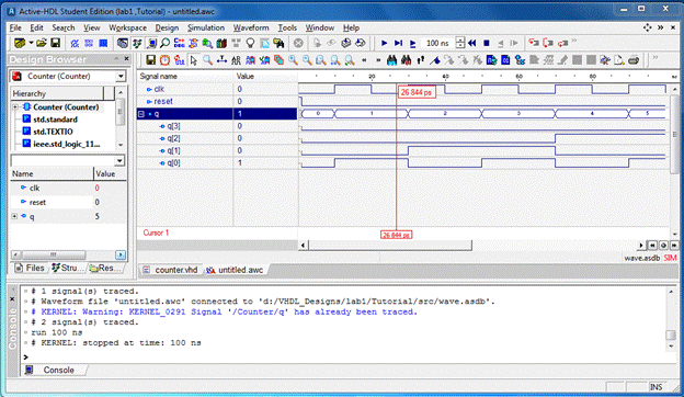
Print your
simulation result and hand it to TA. Your lab 1 is done!
If the simulation result is what you want, congratulation! You can
design your own device now! Why not try a new design? What should you do if you
want to design a Decade-counter with a synchronous reset signal?
Questions: - (The solutions are to be submitted to
your TA within 1 week of your Lab. Limit your answers to a max. of 2 Pages,
including figures, typed single side with 1.5 line spacing and size 12 fonts in
Times New Roman format.)
1. What is the difference between FPGA (Field
Programmable Gate Array) and CPLD (Complex Programmable Logic Device)?
2. What roles do EDA, FPGA and CPLD play in
digital design.